SNOM/SNOMIPEDE
Snomipede races to solve the mysteries of life
Nanotechnology : February 15, 2005
A multi-disciplinary team of scientists from the Universities of Sheffield, Nottingham, Manchester and Glasgow has been awarded a £3m research grant to develop a new nanotechnology tool which they have called the ‘Snomipede’. The team, led by Professor Graham Leggett at the University of Sheffield, hopes that once developed, the Snomipede could enable advances in areas as diverse as the understanding of the origins of disease and the low-cost commercial manufacture of plastic computer chips.
The Snomipede will enable scientists to create tiny molecular structures on scales as small as 13 nanometres.
Once developed, this pioneering new technology will have a multitude of uses in both medical research and commercial manufacturing. In the field of medical research, the ability to construct tiny arrays of biological molecules will enable scientists to conduct extremely sensitive analysis of biological samples. This type of detailed analysis could be used to understand how the human genome – the genetic information in all of our cells – regulates the production of proteins, perhaps holding the key to developing new treatments for common diseases. In addition the Snomipede may provide new tools for studying biological systems at the single molecule level, and enable the manufacture of miniaturised plastic electronic circuits.
Professor Graham Leggett of the Department of Chemistry at the University of Sheffield, and Project Leader of the new research, welcomed the grant saying, “This research grant will allow my team in Sheffield, together with teams at Glasgow, Nottingham and Manchester universities, to pioneer faster, smaller and more efficient methods of manipulating and building molecular structures.
“The development of Snomipede technology represents the coming together of nanotechnology, molecular and cell biology, microsystems engineering and synthetic and surface chemistry. We anticipate that our research will pave the way for cost-effective commercial production of the plastic electronics of the future.
“The implications of the Snomipede will also be far-reaching in the world of medical research. The new technology can potentially be used in the fields of tissue engineering and protein research. These applications will enable researchers to develop a better understanding of disease, human tissue and human genes.”
The term ‘Snomipede’ was coined at the University of Sheffield to reflect the fusion of ‘millipede’ technology (first developed at IBM) with scanning near-field optical microscopy (SNOM).
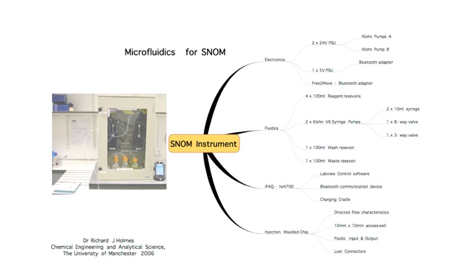
Fluidic Delivery System for Scanning Near Field Optical Microscopy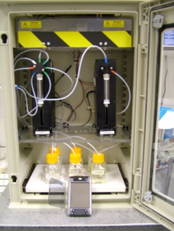
Flow Cell
The flow cell is fabricated from polystyrene using the mould pattern shown below.
This gives an inlet and an outlet located at each end of the device, parallel to the flow of fluid, thus providing relatively easy access for interfaces whilst the device is used with the NSOM. The central chamber is 10mm x 10mm x 3mm (l,w,d), and is open to allow access for the NSOM probe tip.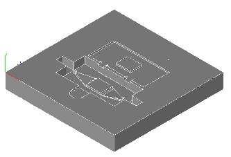
Fluids enter the chip to one side through a luer connector, and flow along the narrow (1mm2) channel until they approach the central well. As the channel widens from 1mm to 10 mm, it becomes shallower with final dimensions approximating 0.75mm x 10 mm. This provides for a laminar flow into the central chamber.
The device is sealed using ultrasonic welding, which forms a watertight seal around the fluidic system by means of energy conductors moulded into the final device design.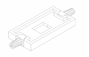
Free2Move Bluetooth Serial Adapter
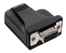
This device is powered from a 5V PSU, connected to the USB port on the rear of the system. There are no data channels connected to this USB port.
NB: A null modem connector is also used to interface the Bluetooth serial adapter with the fluidic system.
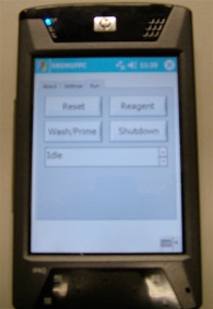
Controller - HP HX4700 iPAQ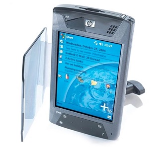
Processor: Intel® PXA270 Processor 624 MHz
Operating System: Microsoft® Windows Mobile™ 2003 SE Pocket PC
Memory: 192 MB total memory;
Display: 4" Transflective VGA TFT color display
Interface: USB 2.0, Infrared (SIR and FIR), Bluetooth, WiFi (WLAN 802.11b) Dimensions and Weight: 131 x 77 x 14.9mm and 210g
Power: 100 to 240 V Switching PSU
Battery: 1800 mAh Lithium-Ion rechargeable battery (user replaceable)
Expansion: SD card slot, supports MMC and SDIO cards, CF Type II card slot
Software - Activating Bluetooth
1.Go to Start Menu --> Settings --> Connections tab.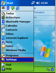
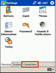
2.Select iPAQ wireless and turn on Bluetooth.
3.Select Manager option.
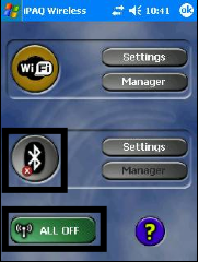
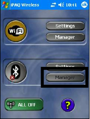

4.Double tap on the Free2Move icon to connect to and activate the Bluetooth serial adapter.
5.Go to start menu --> File Explorer --> and double tap on SNOM1PPC to load the program.
6.Select the settings tab to set the reagent and wash speeds, and then the run tab to select the desired function.
Solvent Delivery System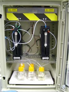
1 x Thalassa Enclosure with glass front
(H430mm, W330mm, D200mm)
---
2 x Puls Miniline 24V PSU
1 x Omron S82K series 5V PSU
1 x Earthing Din Connector
6 x isolator Din connectors
1 x Mains fused socket
1 x Mains rated illuminated rocker switch.
---
2 x Kloehn V6 Syringe Pumps
2 x Kloehn 10ml calibrated syringes
1 x Kloehn 3 way distribution valve
1 x Kloehn 8 way distribution valve
---
6 x 100ml solvent reservoirs
Kloehn V6 Syringe Pumps
The V6 Module is a full featured, ready-to-use syringe pump with extra built-in capabilities. Simply add a 24 VDC power source and a control command logic (via RS485 or RS232) and this module is ready to perform. Designed to be the ultimate in versatility, the V6 Module has the following standard features and capabilities: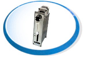
Highest Resolution and Precision - select either 24,000 steps (for normal applications) or 48,000 steps (for smallest volumes) of resolution for each full syringe stroke.
The use of an eight way distribution valve on the feeder pump allows for inlets from four independent solvents and flow these from the syringe to the device. There will also be a direct channel to waste to allow rapid change of solvents. The final spare inlet may be utilised for a device rinse solution. The second pump, working in the opposite direction to the feeder pump will utilise a three way valve, allowing it to draw solvents from the chip into the syringe and then empty to waste as required
8-Way Distribution Valve 3-Way Distribution Valve
Dispensing Pump Withdrawing Pump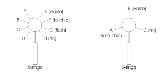
Pump Control System - Key
Home --> Syringe empty
Max --> Syringe full
DS --> Dispensing syringe
WS --> Withdrawing syringe
A – H --> Ports on 8-way valve
A* - C* --> Ports on 3-way valve
DV --> Dispensing Valve
WV --> Withdrawing Valve
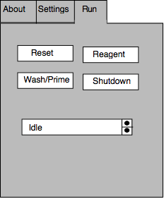
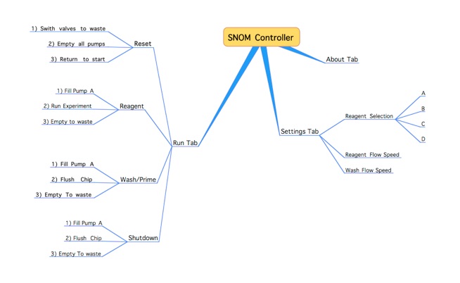
The control system is divided into two tabbed screens on the iPAQ, with one being used for the activation of the run-time routines and the other or settings required by each programme.
Finally, an activity indicator is included on the front panel display of the palm to signal a run in progress.
Important: All pumps are automatically returned to the Home position before any operation. Therefore the final stage of any programme is an “empty to waste and return to the home” function. All pumps are at the home position and all valves are at waste position before every run
Also, a reset command will be included which will all pumps are at the home position and all valves are at waste position before every run.
Reagent Cycle
The reagent cycle allows for a selection for four different solvents, with a pause function and a stop function which terminates the programme, empties the syringe system and returns the system to home in readiness for the next run.
1) Select solvent on iPAQ
*Use settings pane to select solvent channel*
•DV moves to solvent channel (A – D)
•DS filled to 10%, pauses for 10 seconds to equilibrate pressure.
•DV moves to waste position (E) and empties.
•DV moves to wash channel (G).
•DS fills to max position at pre-determined speed (rapid).
•DV moves to chip channel (F).
•WV moves to chip channel (A*).
•DS and WS activate (DS Chip WS) at pre-determined speed.
2) Select Pause on iPAQ
•DS and WS pause
•No change in DV and WV
3) Select Pause on iPAQ
•DS and WS re-start
•No change in DV and WV
4) Select Stop on iPAQ
•DS and WS halt.
•DV and WV switch to waste channel (DV E and WV B*)
•DS and WS drive to home position and empty to waste.
Wash / Prime Cycle
The wash / prime cycle allows unwanted reagents to be removed from the chip side of the system by washing, and primes the system with liquid before a run is conducted.
1)Select Wash on iPAQ.
•DV moves to wash channel (G).
•DS filled to 10%, pauses for 10 seconds to equilibrate pressure.
•DV moves to waste position (E) and empties.
•DV moves to wash channel (G).
•DS fills to max position at pre-determined speed.
•DS pauses for 10 seconds to equilibrate pressure.
•DV moves to chip channel (F)
•WV moves to chip channel (A*)
•DS and WS drive at pre-determined rate
•Once DS reaches home, WS halts.
•DV and WV switch to waste (DVE and WV B*)
•DS and WS drive to home position and empty to waste
2) Select Pause on iPAQ
•DS and WS pause
•No change in DV and WV
3) Select Pause on iPAQ
•DS and WS re-start
•No change in DV and WV
Reset Cycle
The reset cycle switches both valves to waste ands empties both syringes to waste, returning them to the home position in preparation for a fresh run. This is required in case of instrument or power failure.
1) Select Reset on iPAQ.
•DV moves to waste channel (E)
•DS returns to home position empties to waste at pre-determined speed
•WV moves to waste channel (B*)
•WS returns to home position empties to waste at pre-determined speed
2) Select Pause on iPAQ
•DS and WS pause
•No change in DV and WV
3) Select Pause on iPAQ
•DS and WS re-start
•No change in DV and WV
Shutdown Cycle
This cycle allows for a complete shutdown of the system.
2) Select shutdown on iPAQ.
•DV moves to wash channel (G).
•DS filled to 10%, pauses for 10 seconds to equilibrate pressure.
•DV moves to waste position (E) and empties.
•DV moves to wash channel (G).
•DS fills to max position at pre-determined speed.
•DS pauses for 10 seconds to equilibrate pressure.
•DV moves to chip channel (F).
•WV moves to chip channel (A*).
•DS and WS drive at pre-determined rate.
•Once DS reaches home, WS halts.
•DV and WV switch to waste (DVE and WV B*).
•DS and WS drive to home position and empty to waste.
Thus all systems are rinsed and free from contaminates, both syringe pumps are returned to the home position and the valves are switched to waste before shutdown can occur.
Settings Screen
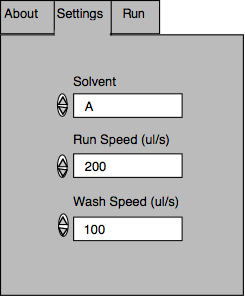
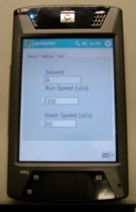
The three options on this screen allow the user to dictate a delivery speed for the solvents to the chip, and also during the wash. The software will incorporate a range of speeds available to the user, specifically with a top end defined to prevent damage to the system.
Fill speeds for the syringes are set to maximum since this does not disturb the working of the instrument.
Finally, there will be the option to determine which of the four available solvents is to be dispensed.
Acknowledgements
Instrument development
•Labview software designed by RJ Holmes & BJ Treves Brown
•Injection moulded flow chip designed by RJ Holmes & NJ Goddard
•Electronics and fluidics system designed by RJ Holmes and BJ Treves Brown
•Additional information relating to NSOM and integration with existing instruments - GJ Leggett, R Manning, S Sun, and N Lu.
Software Controller Schematic
Instrument Details