Lab-on-a-Chip - Optical Systems
Integration of Grating coupled detector device into Lab-on-a-Chip system.
Equipment:
Optical Grating
•Fabricated by Epigem Ltd. 1/10/01
•964 lines/ mm grating
•14.6 Blaze angle at 520nm Blaze wavelength
•Grating hot embossed into PMMA,
•Coated with gold to 79 nm.
•EP36/39/4 and EP36/39/5
Light Source
•473nm Frequency Doubled SS Laser – Laser 2000
Micro-Channel
•Polystyrene Injection moulded ridge channel
1) Fabrication of Micro channel:
The micro channel was fabricated using injection moulding onto a brass mould, prepared using a Datron CAT 3DNC-milling machine. The channel dimensions were 200micron by 200micron by 30mm. There was a raised ridge around the channel, 100mm wide, which was used eliminate problems seen with previous systems where any bonding method resulted in a blockage of the channel. The channels were fabricated from polystyrene, with 4 channels per device. These were then cut into two sections, two channels on each and once channel was used over the electrodes, the second channel was not utilised.
2) Bonding of the channel to a substrate.
Bonding the channels required the use of an adhesive, which could be used between he plastic and glass surfaces of the components. The major difficulty was using an adhesive, which could be easily applied and resulted in a rapid seal around the channel.
A low viscosity cyanoacrylate glue (Hot Stuff –FM570, Craft Supplies Ltd, UK) was obtained and used to seal the polystyrene chips to the grating slides. Due to the nature of the glue, it was possible to flow the glue around the ridged structure, ensuring even coverage, and simply bond the two components. This gave a success rate of 99%, with problems only arising if the components were knocked before the glue had time to set. Previous experiments had shown that once bonded, the seal was capable of withstanding flow rates in excess of 4 ml minute, giving a linear flow velocity of 1.112 m S-1 for the channel dimensions (using a Kontron HPLC pump). The weakest part of the device being the connection wells required for interface with the outside world. This problem was solved using araldite adhesive to secure the tubing in place.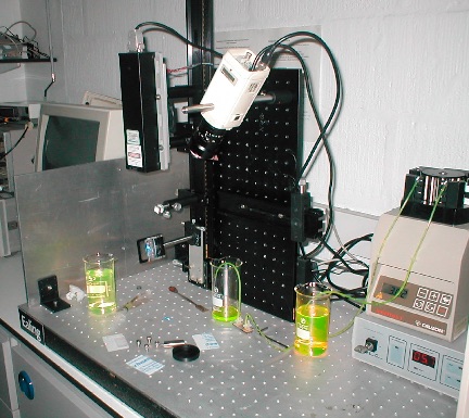
The device was fabricated by machining the Epigem Grating into 3 separate pieces, and attaching a microflow channel to this using
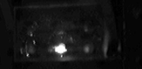
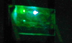
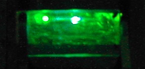
Using the Grating at an angle of approximately 60° from normal, waveguiding using an injection moulded grating is illustrated.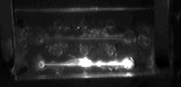
Using a Weak Fluorescein Solution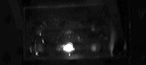
At 0° to laser incidence at 20° to Laser incidence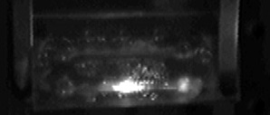
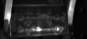
a 40° to Laser Incidence At 60° to Laser incidence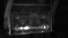
at 80° to Laser Incidence
Using a Digital colour Camera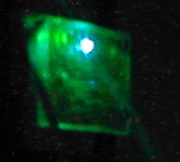
0° from Normal 20° from Normal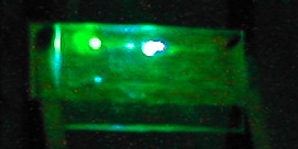
40° from Normal 60° from Normal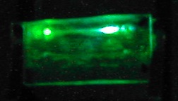
80° from Normal